
two essential functions
The expansion tank:
The expansion tank serves two functions within an HTF system. First, it accommodates the expansion of the fluid as it heats up, and second, it collects and removes the low-boiling fractions from the system.
The fluid expands by approximately 10% of its total volume for every 100°C. If the system is heated to 300°C, you must therefore account for an expansion of approximately 30% of the total system volume.
To limit oxidation and degradation of the liquid caused by contact with oxygen and moisture, the expansion tank is equipped with an inert gas system, typically using nitrogen. When the system is purged, the nitrogen pressure in the expansion tank is reduced to 0.1 bar, allowing the low-boiling fractions to condense safely and be collected in a condensate tank. Low-boiling-point fractions and moisture end up in a cold seal tank, which must be regularly emptied and inspected as a standard part of the maintenance program. Read all about expansion tanks in our blog “Thermal Oil Information: Everything You Need to Know.”

Filters
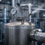
Thermal systems are typically equipped with a coarse filter in the main flow that traps bolts, nuts, and other construction debris after the system has been installed. Modern systems often also feature a fine filter in a bypass configuration.
A fine filter like this removes insoluble degradation products from the fluid, keeping it clean, maintaining turbulent flow, and potentially extending the fluid’s service life by several years. The filter elements must have a pore size of 5 to a maximum of 50 microns. Do you have an older or contaminated system? If so, please contact us for advice.
Gaskets
For high-temperature thermal systems with flange seals, only graphite gaskets may be used. All other gasket materials will eventually leak when synthetic thermal fluids are used.
Boilers
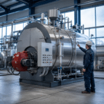
The boiler is an essential component of any HTF system and can be either electric or gas-fired. The service life of the heat transfer fluid is optimized when the right balance is achieved between heating capacity, temperature, and fluid flow rate.
The boiler capacity, in combination with the pump capacity, largely determines how long the heat transfer fluid will last. The correct choice of fluid depends on the application and, in particular, on the operating temperature. The maximum film and bulk temperatures for each type of Fragoltherm® and Therminol® can be found in the corresponding product brochures.
Insulation
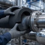
Organic heat transfer fluids, such as our HTF fluids, can undergo a slow oxidation reaction with air at fluid temperatures above 260°C in the presence of insulation material.
Porous insulation, such as calcium silicate, provides a larger reaction surface with poor heat dissipation. Combined with possible catalysis by the insulation material, this can cause a temperature rise that may result in the liquid igniting as soon as the saturated insulation comes into contact with air, for example during repairs. This phenomenon has not been fully explained, but does not appear to occur with cellular glass, possibly due to its closed-cell structure.
Therefore, use cellular glass in all areas where leaks are possible, particularly around instrument connections, valve gaskets, flanges, and other sealed surfaces. As a precaution, address any source of leakage immediately: replace leaking gaskets and oil-soaked insulation, re-pack valve stems, and cover insulation where leaks may occur with metal covers. Where possible, install valves with the stems horizontal so that leaking oil can drain away from the insulation. Sensors and protective devices against spray leaks at flanges are standard features of our product line.
Flanges
The layout of the piping system for HTF heat transfer fluids must be designed to achieve the required flow rate at an economical pressure drop. Because the system is subject to temperature fluctuations, sufficient flexibility to accommodate thermal expansion and contraction is essential; mild carbon steel (40) or an equivalent material is used throughout the system.
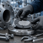
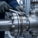
Most organic liquids tend to leak through flanges and fittings unless they are tightly and properly installed. Welding all joints is the best way to prevent pipe leaks; where access is necessary, flanges with weld neck connections are recommended.
To ensure proper installation and sealing of spiral-wound gaskets in HTF fluid lines, follow this procedure: Clean the flange surfaces of loose rust, dirt, and weld spatter, and check that the surfaces are free of protrusions or grooves and are properly aligned—gaskets cannot correct these issues. Check studs and nuts for rust and thread debris, and lubricate the threads. Bolt and torque values are specified by the gasket supplier and depend in part on the gasket’s diameter and thickness. Tighten the opposite studs or bolts in small increments to the required torque value, in the order of 9, 3, 6, and 12 o’clock, and repeat this with the adjacent bolts.
Pumps
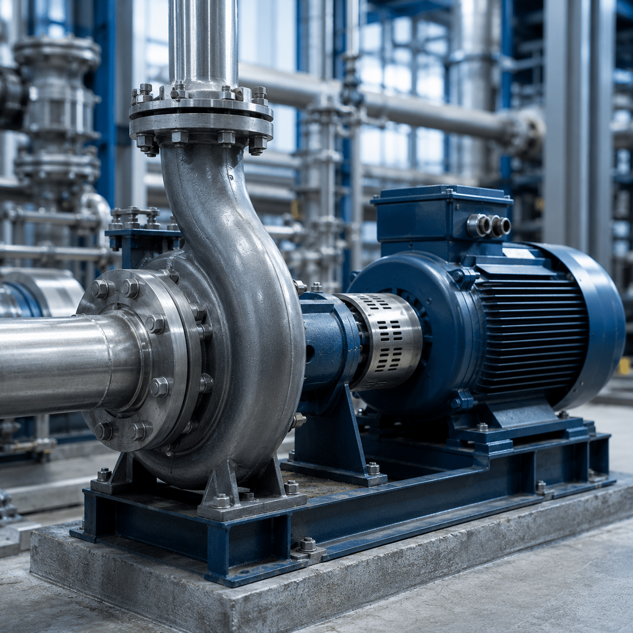
The pumps in an HTF system must have sufficient capacity and head to circulate the fluid at the required flow rate. These are typically centrifugal pumps—sometimes with sealed bearing systems or magnetic drive—that meet the required standards.
In most systems, the pump housing is made of cast steel or other materials suitable for very low or high temperatures. For temperatures above 200°C, pump manufacturers typically specify water-cooled mechanical seals, or, preferably, liquid or air cooling with an extended shaft seal and bearing.
Pumps with a stuffing box seal must contain at least five rings of laminated graphite packing. Inert flushing of the seals with steam or nitrogen prevents the buildup of oxidation byproducts, which could otherwise lead to leakage. A secondary seal provides additional safety in the event of a sudden sealing problem. Check the flow rate regularly against the original pump characteristics.
Avoid improper pipe support, as this can put stress on the pump bearings and lead to misalignment and leaks. Equip each pump with a temperature sensor that automatically shuts off the pump in case of problems. If you use expansion loops in the pump section piping, orient them horizontally or vertically downward—never vertically upward, as this creates a trap that collects air and vapor and can impair pump capacity.

Valves
For HTF systems, forged steel valves with deep stems are sufficient. Use butterfly valves and ball valves with external threads throughout the entire heat transfer system; keep in mind, however, that butterfly valves do not always provide an absolute seal.
Various types of gaskets are used to seal valve stems in high-temperature systems; generally, five rings per valve stem are recommended to ensure a proper seal. Bellows-type stems provide virtually leak-free operation.